-40%
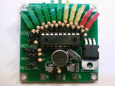
11-Segment VU Display Meter >>KIT<<- US SELLER
$ 7.91
- Description
- Size Guide
Description
This sale is forONE
5cm x 5cm breakout board VU Display Meter
>>KIT<<
You put it together.
Please Note this does require some soldering skills.
Instructions:
Complete Assembly Instructions
When I designed and put this kit together, I wanted something with a retro style look but with a twist on the features instead of just an ordinary DOT/BAR display driver. This display also has a unique DIGITAL feature that allows for direct auto baud detecting serial communication to control each LED individually. It also has an optional PEAK
indicator with a 2 second delay. You will also notice 11 segments, where most displays have only 10 segments. I did this on purpose for applications where DIGITAL control was used.
With a background in electronics and computer programming for over 30 years, it has always driven me a little nuts that you can't easily represent a “centerâ€
ン
indicator position. With an odd number of segments the center position can easily be represented. This poses another challenge I had to overcome. The PIC16F54 micro-controller used in this design only has 12 general purpose I/O's (Input/Outputs) and does NOT have an ADC (Analog to Digital Converter). Without an internal ADC, it makes it difficult for a built in microphone to detect audio.
The solution here, with one pin to spare, was to implement a software driven 1-pin sigma delta ADC. Wait? A 1-pin sigma delta? Yes, typically a Sigma Delta ADC uses 2 pins one for the feedback and one for the drive. The idea is that the feedback pin reads one I/O and drives another I/O pin in the opposite state. A neutral situation where there is no analog input would cause the feedback and drive pin to oscillate with a 50% duty cycle. Any external influence on the analog signal line would create a bias on the oscillations to be something other than 50%. That is the basics of a sigma delta ADC, to monitor and report the amount or error deviation from a 50% duty cycle signal from the Feedback and I have combined the Feedback and Drive into one pin with this design while also eliminating the need for any external pre-amplification from the electret microphone. The MODE selections are detected at power-up and utilizes some of the same I/O's that drive the LED segments.
I hope you enjoy your VU display and have fun putting your kit together.
Video link to the finished product in various configuration modes....
You Tube Video Code: mtIMUpxE1CI
<-- Just go to YouTube and plug this into the search
Features:
- 7V to 12V DC input voltage
- Built-in microphone
- Analog input
- Standard DOT/BAR display mode
- Peak Detector (2 second decay) works with both DOT/BAR
- Direct Digital control - connect to a micro controller for individual segment control. Auto baud detection from 300 baud to 57.6k baud.
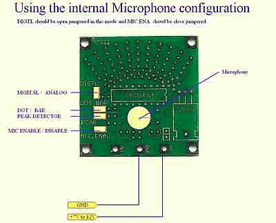
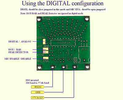
(Note: See eBay images for wiring configuration info in different operation modes)
Inverted 8N1 2-Byte DIGITAL Communication scheme Syntax:
First BYTE always "!" .. HEX or Decimal 33
Second Byte:
BIT0 to BIT3 Select the LED position ( range = 0 to 11 ; 0 = none )
BIT4 sets the DOT/BAR display mode ; 0 = BAR mode ALL LEDs upto the selected LED positon will be lit
; 1 = DOT mode only LED at the selected LED position will be lit
BIT5 Clears ALL LEDs when set and overrides BIT0 to BIT3 setting
Bit6 is the Output Latch bit ; Update display LEDs when set
Bit7 = Don't Care
Parallax Propeller DEMO code for digital operation:
Download
Video link to DIGITAL demo running ... no sound, just direct light control from a microprocessor.
You Tube Video Code:
WRGHr7sUHaE <-- Just go to YouTube and plug this into the search
